A Gentle Power Off for ZEReader: Replacing the Hard Switch with a Latching Power Circuit
- Anna-Lena Marx
- ZEReader , Electronics , Embedded
- November 16, 2025
Table of Contents
With the second revision, the way ZEReader is turned on and off got a massive redesign.
The hard on/off switch in the first revision was dead simple and worked great—with one big flaw from a user’s perspective. You could not recognize if the reader was on or off on the first sight. The old switch just closed or opened the loop with the power supply, and due to the E-Paper display just holding the state, you had no chance to tell.
Besides, there was no possibility at all to implement some kind of graceful shutdown mechanism, which would allow me to save all important state information and show a clear device off indicator.
This situation was totally fine for the very first prototype, but it started to get annoying very soon. A new approach was needed!
Good and Bad Ideas
My very first intention was to search for some kind of IC to solve that problem. The MAX16150, a nanoPower Pushbutton On/Off Controller and Battery Freshness Seal, read like an exact fit for what I was looking for from a pure technical perspective.
Quote
This device accepts a noisy input from a mechanical switch and produces a clean, latched output, as well as a one-shot interrupt output, in response to a switch closure exceeding the debounce period at PB_IN. A switch closure longer than shutdown period at PB_IN results in a longer one-shot interrupt output. The MAX16150 family has two set of devices, one in which a longer switch closure greater than the shutdown period deasserts the latched output, and another in which the latched output stays asserted.
However, the fixed shutdown period for the MAX16150, depending on the exact model, is between 8 and 16 seconds. That’s pretty long and not really intuitive for a user.
Besides, this rather simple IC is with around €3.3 just too expensive in relation—but it gave me a conceptual idea of how to continue.
Utilizing a Self-Holding (Latching) Circuit
The solution lies in a self-holding (latching) circuit: a circuit that closes the loop to the power supply when a button is pressed and can then hold itself active afterwards. This can be achieved with just a few simple components.
The central elements are two enhancement-mode MOSFETs (one n-channel and a complementary p-channel one) and two switching elements.
The Falstad CircuitJS Simulator helps to visualize the idea and functionality. You can try out the simulator yourself later in this post, but let’s start with an explanation first.
The Initial Situation (Off State)
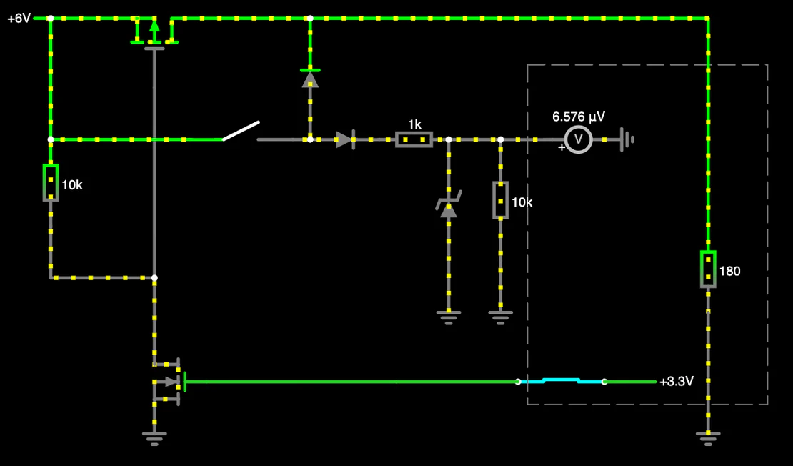
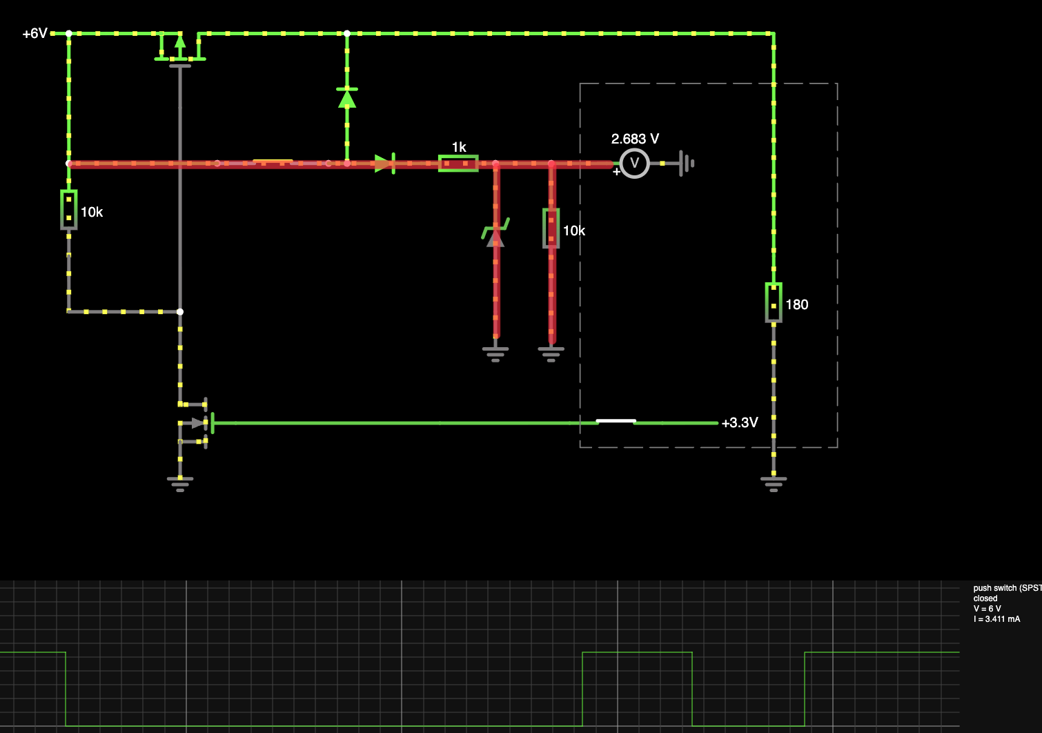
The following picture, taken from the CircuitJS simulator, shows the circuitry for the new on/off mechanism in its initial (off) state.
The dashed box represents the microcontroller (MCU), which the self-holding circuit attaches to via two GPIOs. The top connection is a GPIO input, used to record and interpret the physical button input, while the second one, a GPIO output represented as an internal switch, is used to actually control the power flow.
In the pictured initial situation, the hardware button (top left) as well as the internal one (the output GPIO) are open and both MOSFETs are off (blocking). The enhancement-mode p-MOSFET in the top of the picture is blocking because its control voltage \(V_{GS} \approx 0\) (its gate is pulled high). It will become conductive if \(V_{GS}\) gets negative. The enhancement-mode n-MOSFET will conduct on a positive control voltage \(V_{GS}\), which is also \( \approx 0\) right now.
Getting the Microcontroller Started…
Following the well-known pattern from other electronic devices, I’d like the device to start up and shut down again on a long press on the power button. Fortunately, this behavior is perfectly depicted by the shown circuitry.
As long as the user button in the top left area is pressed, current flows via the button and the diode pointing upwards into the microcontroller. This causes the MCU to start up and initialize itself and the peripherals in less than a second.
At the same time, the GPIO input will detect a logical one with a level of \( \sim 2.7 V\), which is limited by the Zener diode for protection, as the input voltage is usually assumed to be \(5 V\).
The \(10 k\Omega\) resistor in parallel is a pull-down to ensure defined logic levels and avoid getting trapped with the Raspberry Pi Pico 2’s E9 Bug.
… And Keep it Running
To keep the device running without the need to keep the button pressed, the GPIO output must be set to high (\(3.3 V\)).
Depending on the desired behaviour, it is up to the application software to decide whether this should take place as soon as the boot up reaches a certain stage or if the input GPIO should additionally be evaluated.
With this output GPIO (represented by the switch down right) set to high, the n-MOSFET in the lower left area becomes conductive (its \(V_{GS}\) got positive). This action pulls the gate line of the p-MOSFET above to ground, making its control voltage \(V_{GS}\) negative. Thus, the p-MOSFET becomes conductive.
The self-holding circuit is now up and driving the microcontroller, independent of the user on/off button press.
Interrupts
As long as the self-holding circuit and thus the device are active, the on/off button becomes a usual interrupt source from the microcontroller’s point of view.
Depending on the intended device behaviour, the software implementation could also listen for common, short button presses and use the button like everyone else.
A Gentle, Software-Defined Shutdown
With the pictured circuitry, shutting off the device means toggling the output GPIO (switch) in the lower right to zero again. When this happens is completely defined by the microcontroller’s software.
To reach the intended behaviour, the ZEReader firmware utilizes Zephyr’s input-longpress infrastructure. This makes the required button press time easily configurable, and a gentle shutdown routine can be started from the longpress callback function.
This allows me to implement a proper shutdown routine, for example, saving the current reading state, showing a logo or some other kind of shutdown screen to make clear the device is off now, or even asking for pressing another button to confirm turning the device off. As long as toggling the output GPIO is the last step, the shutdown behaviour before can be feely defined, matching the target application.
Try out the Simulator!
Time to play around with the circuitry at your own!
Click around in the interactive simulation and observe the behaviour.
But does it also Work in Real-Life?
Sure!
Update 2026-02-01:The v2 PCB is not finished yet, but circuitry was tested with a simple breadboard setup to verify it and develop the software side..
The v2 PCB works great!
(If you do not introduce software issues between the breadboard testing code and the actual ZEReader firmware…)
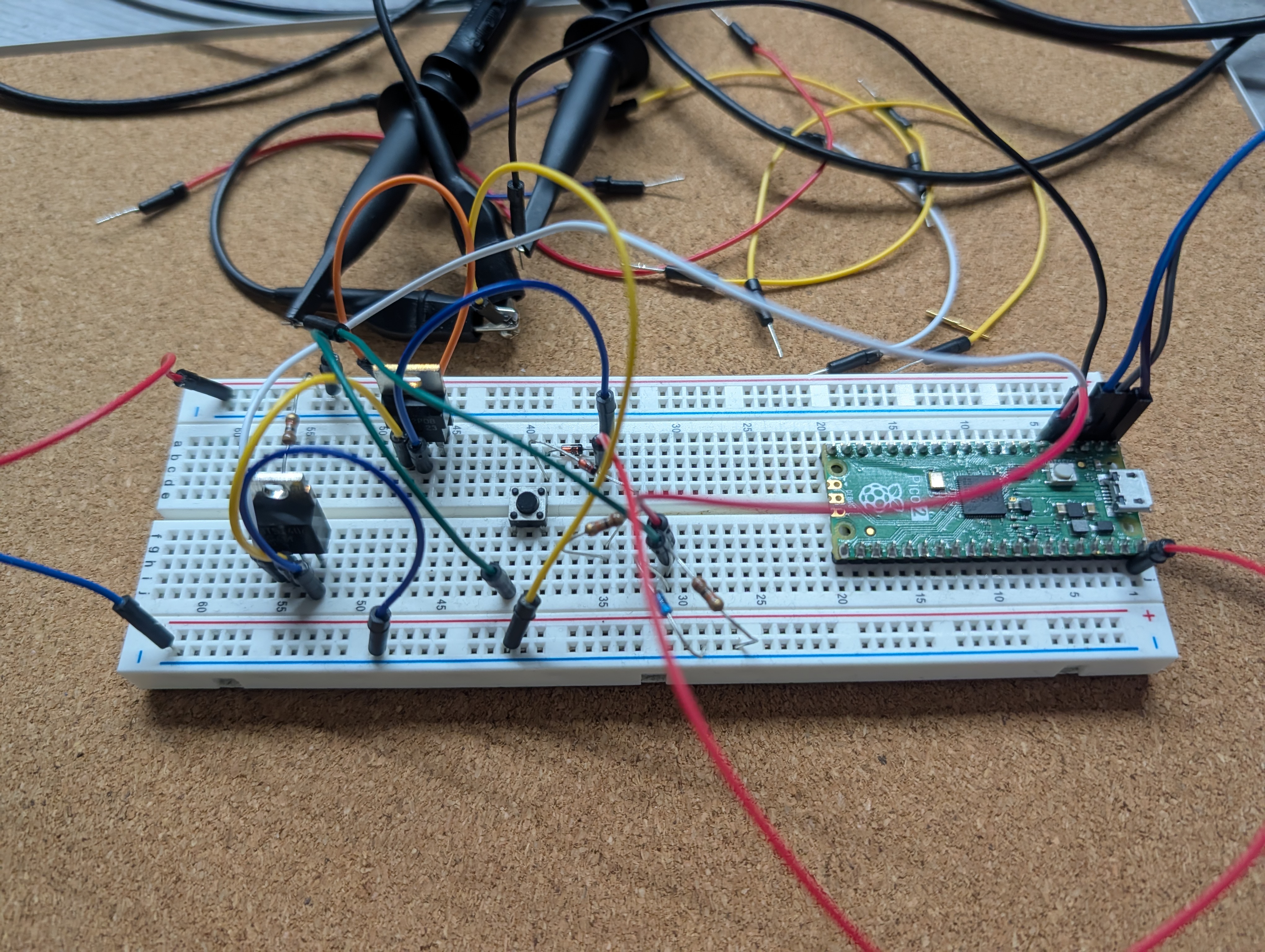
A quick check with the oscilloscope helped me check for the expected voltages. The Pi Pico can deal with a surprisingly wide range, but with the E9 bug still active for my board and not trusting the app note stating the inputs are \(5V\) safe, it was better to actually verify the button’s input signal quality and level and measure through the whole setup.
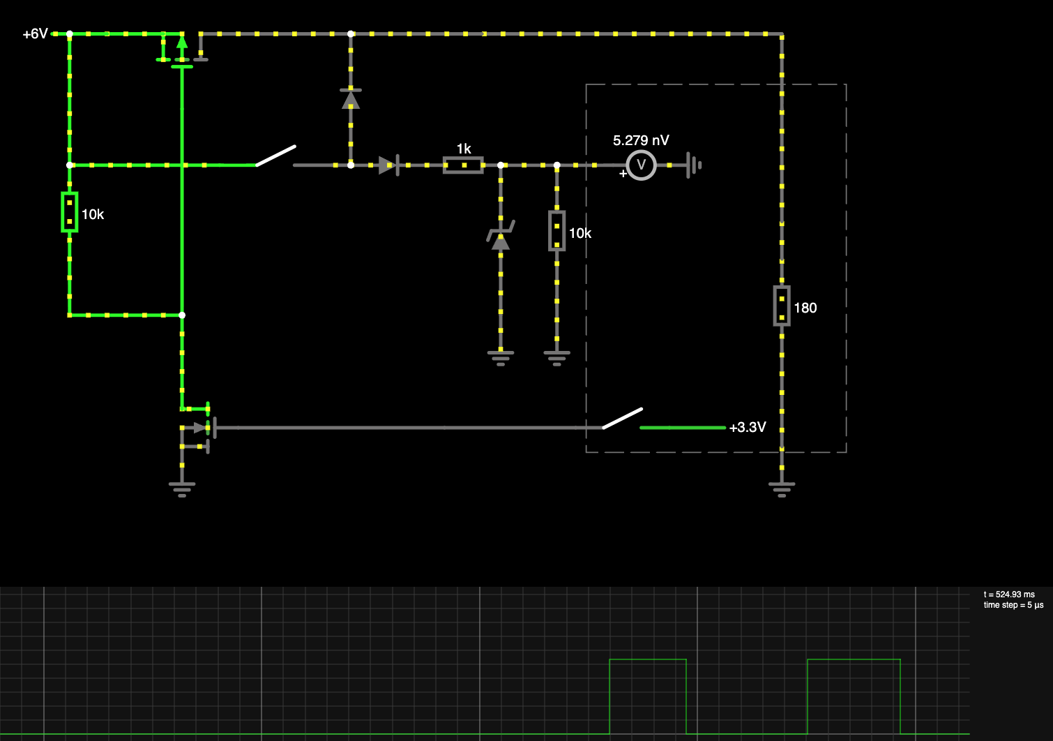
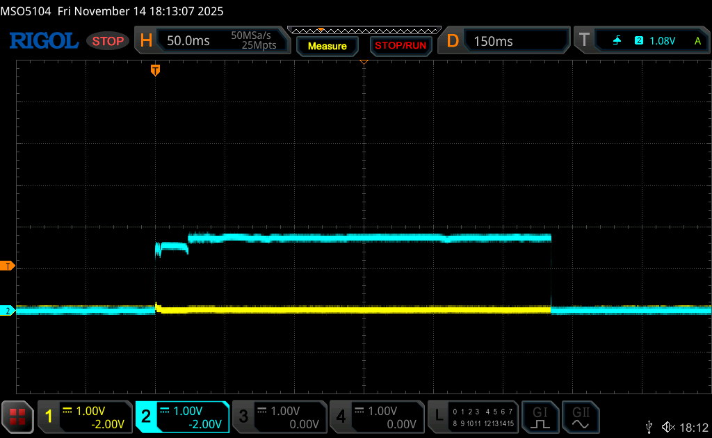
Trace 1: A Failed Latch
This first oscilloscope screenshot shows a single short button press in the circuit’s initial off state (Channel 2, blue). The button press is fine and can be registered, the microcontroller starts its work, but in this case, it was below the configured threshold to start up completely. The microcontroller did not yet set its output GPIO (Channel 1, yellow) to high, thus the self-holding circuit was not activated.
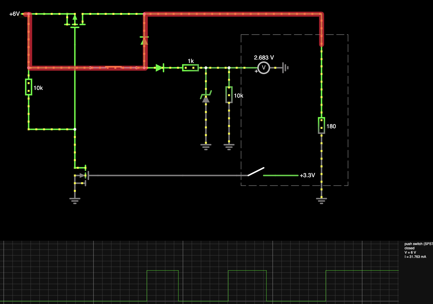
Trace 2: Active Interrupt
The next screenshot pictures the situation with the self-holding circuit already activated. A (short) button press without toggling the controlling output GPIO is completely independent and does not interfere with the power path.
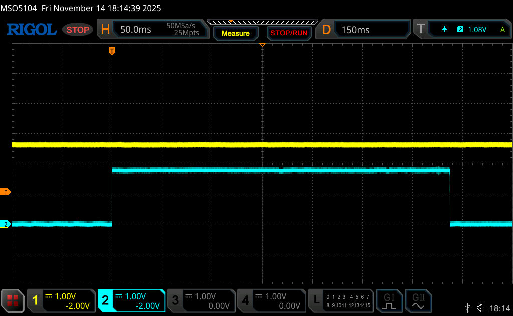
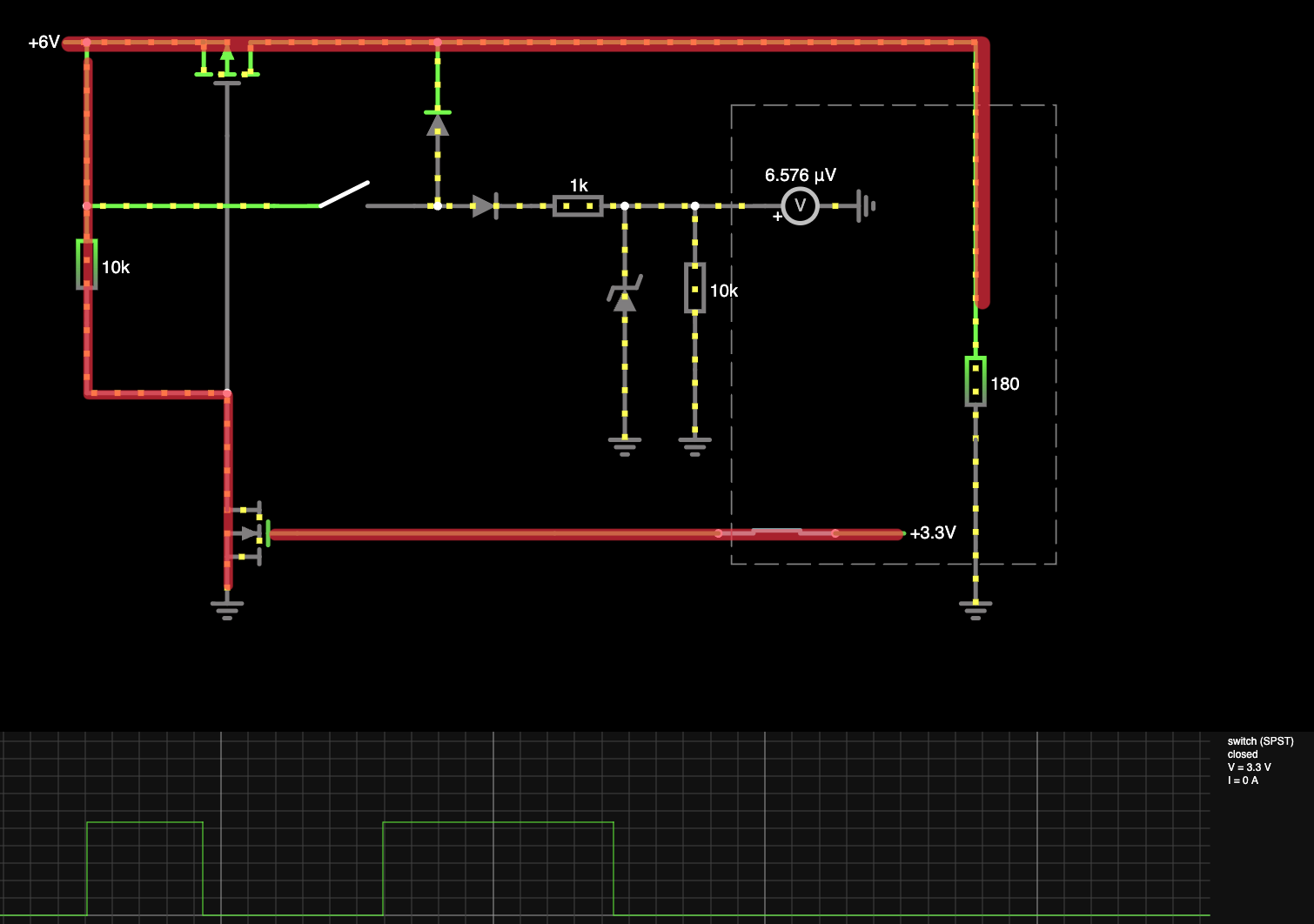
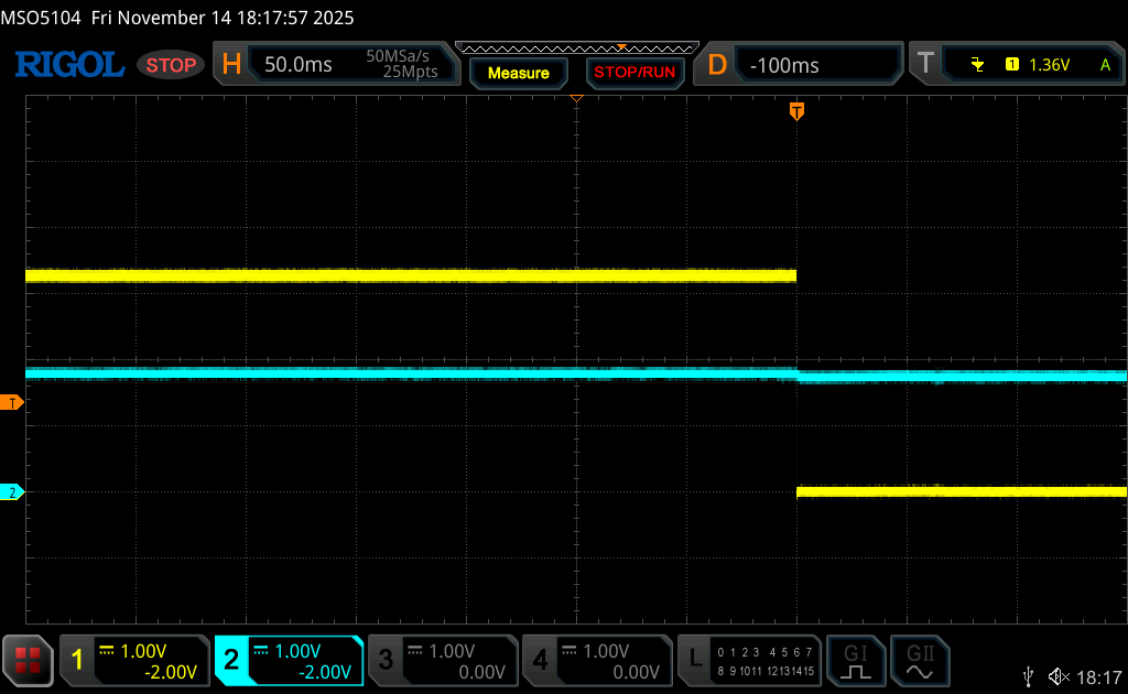
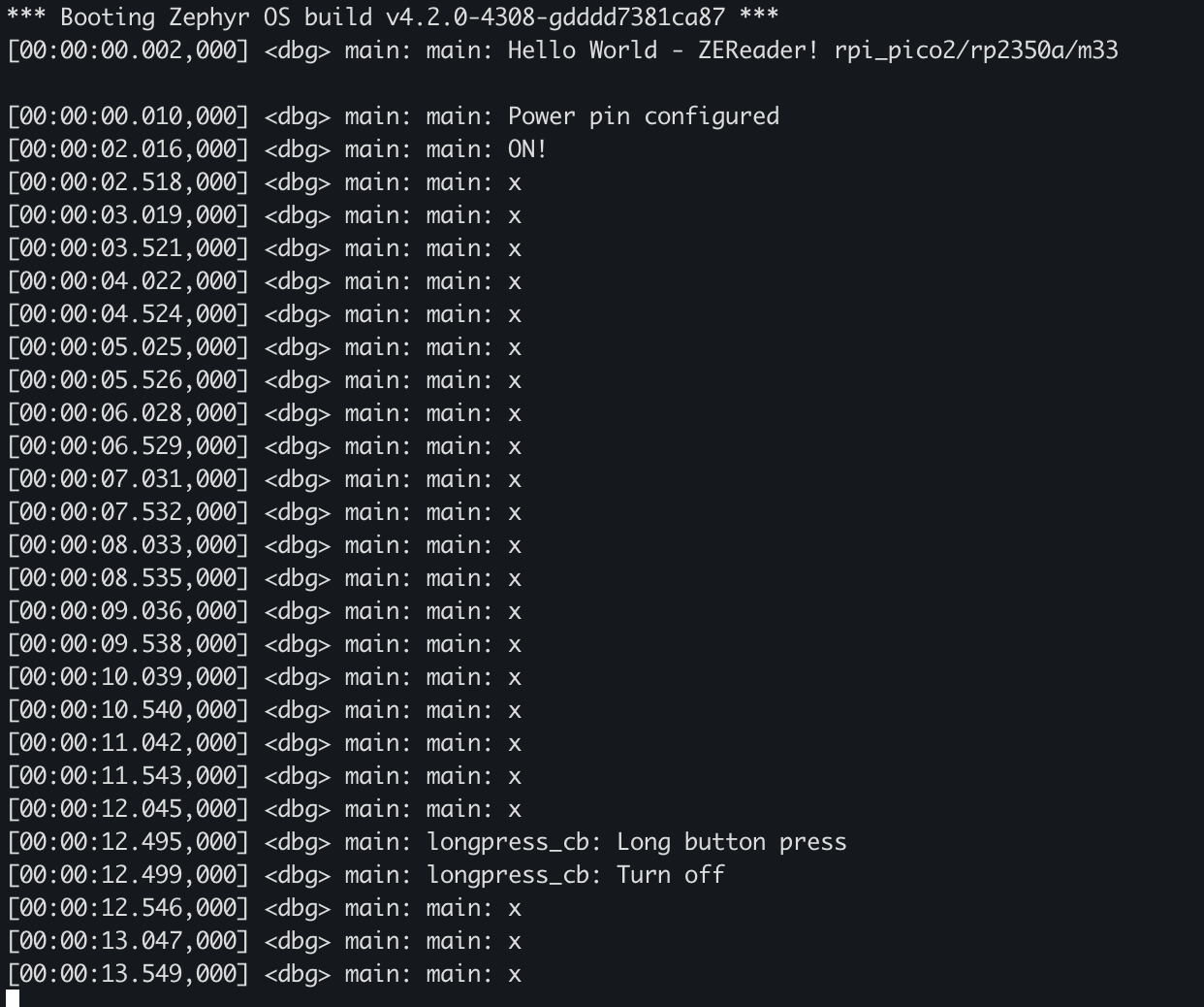
Trace 3: The “Hold-On” Shutdown Behavior
At last, I want to point out to a maybe surprising, but logical behaviour you can see in the following last oscilloscope screenshot, which is also confirmed by the software log screenshot.
With a long button press registered, the controlling GPIO output is toggled as expected (Channel 1, yellow) — but the device does not stop immediately, even if the power off routine is finished (a printed ‘x’ means the software is running).
As long as the on/off button is pressed, the device is still powered through the direct path described above, and thus alive and still running. Only when the button is released, it is actually turned off (and thus no logs are printed anymore).
Related Posts

USB Updates - Challenges, Approaches and Practical Tips
- Anna-Lena Marx
- February 24, 2024
- Embedded , Conferences
Over-the-air updates have established themselves as the standard for networked devices, but the effort involved in operating the server side is not always commensurate with the benefits. In such cases, the supposedly simple and quick solution of implementing updates via USB is often chosen. But is it really always that uncomplicated? What considerations are necessary to implement USB updates effectively?
This presentation provides an insight into the challenges of USB updates and presents solutions and practical tips for successful implementation. Find out which aspects need to be considered in order to optimize USB updates and ensure a smooth process
Read Post
International Women's Day - Why I wear Yocto Shirts on the Embedded World Exhibition
- Anna-Lena Marx
- March 8, 2024
- Personal , Embedded
Today, on the occasion of International Women’s Day, I’d like to give you an insight on working in Embedded as a woman: Why I’m searching for my best Yocto shirt and the nerdiest hoodie when I’m visiting the Embedded World exhibition.
Let’s go back some years to one of my first Embedded World visits. I was still a student doing my master’s degree in Embedded Systems. EW traditionally invites embedded students from all over Germany and adjacent countries on the third day, the student’s day. Together with some of my fellow students, I joined the trip and was looking forward to seeing new trends, talking to people, but also getting an idea where to apply for a job after finishing. At the exhibition, I started exploring together with some peers. Of course, all male. When going through the exhibition and talking to the people at the booths, I quickly recognized a pattern. The staff talked rather to the boys than to me. Mostly not quite obvious and probably not even on purpose. I think it’s about internalized stereotypes. They probably do not think that much about it, but obviously I was not a technically competent conversational partner to them at first sight, even if I asked the questions. I was an addition, an accompanying person from university or marketing. Mostly it was rather subtle, and I did not recognize it that much as the problem it was in the actual moment. But at some point we reached the Intel booth. I asked a question on something I was really curious about, and the male staff member started explaining to me and the accompanying students. During his talk, he started turning more to the boys until he showed me his back. I got a bit angry and told him directly that I would really like to hear the answer to the question I asked. Ok, bad, but human. So why am I telling this, and why do I mention Intel? Because I believe particularly such large companies should sensitize their employees working on a booth.
Read Post
LoRaWAN in theory and practice: A trip through Munich
- Anna-Lena Marx
- February 24, 2024
- Embedded , Conferences
LoRaWAN (Long Range Wide Area Network) is becoming increasingly popular, thanks in part to public networks such as The Things Network, which allow users to dispense with their own gateways. LoRaWAN also promises potential in terms of range and energy efficiency. But how does the standard perform in practice?
The aim of the presentation is to shed light on the technical background and demonstrate how practicable LoRa is in the field using real tests. It will be shown how the standard behaves in urban and rural areas, how differences in height of the gateway and different antennas influence the transmission quality.
Read Post